Loop Wiring Diagram
The power feed cable may go to either the switch or the bulbholder. Wiring a switch loop diagram.
Switch Loop Wiring Electrical DIY Chatroom Home Improvement Forum

This diagram illustrates wiring for one switch to control 2 or more lights.

Loop wiring diagram. Of course if you do not wish to run 143 cable the easiest method around the problem is to run the power feed for the light fixture into the light switch. Loop drawings can be customized per customer taste although certain minimum standard information is. It could be connection between:
A switch loop single pole switches light dimmer and a few choices for wiring a outlet switch combo device. Superordinate to the p&id is the process flow diagram (pfd) which indicates the more general flow of plant processes and the relationship between major equipment of a plant facility. The purpose is the very same:
This diagram illustrates wiring for one switch to control 2 or more lights. Loop diagrams are very important instrumentation design deliverable. Similar to grating to remove, replace or repair the wiring in an automobile, having an accurate and detailed loop detector wiring.
Loop diagram represents detailed drawing showing a connection from one point to control system. One cable (l+n+e) either from the mains board or the last ceiling rose, one cable (l+n+e) out to the next ceiling rose, and one cable (l+s/l +e) that goes to the wall or pull switch within that room. A wiring diagram is a simple visual representation of the physical connections and physical layout of an electrical system or circuit.
Loop drawing are mostly drawn on drafting software like autocad but nowadays. Loop diagram will detail the connections of pneumatics and wiring from the field device through any junction boxes or marshalling cabinet to the controller or computer interface which controls the process a single loop or a cascade loop of the process. Redline chevy 7 pin wiring harness wiring diagrams show.
The 2011 nec code requires that the switch loop use wires of the proper color code to signify hot wires. Loop diagrams are the most detailed form of diagrams for a control system and thus it must contain all details omitted by pfds and p&ids alike. From a physical wiring standpoint it will be necessary, at a minimum to.
Electrical loop layout loop detector wiring diagram loop detector operating instructions remote control station pedestal notes operator field installation for assembled gate operator field installation for unassembled gate balance system adjustment and safety warnings spring, cable, and sheave replacement general arrangement & general. Ceiling fan wiring diagram switch loop in 2021 ceiling fan wiring ceiling fan switch ceiling fan with light. A loop diagram will detail the connections of
With smartdraw you can create more than 70 different types of diagrams charts and visuals. The shorted turn effect of the single wire coil in the proximity of the loop acts much like a shorted turn secondary of a transformer. Correspondingly, what is a loop sheet?
This standard does not mandate the style and content of instrument loop diagrams but rather it. Wiring a switch loop diagram. When a loop diagram shows you exactly what wire color to expect at exactly what point in an instrumentation system, and exactly what terminal that wire should connect to, it becomes much easier to proceed with any troubleshooting, calibration, or upgrade task.
6 best wiring diagram software for your business 1. Field instrument to control system (or vice versa) signal from control panel to control system (or vice versa) know more about it here. Loop diagrams are fairly constrained in their layout as per the isa 5.1 standard.
Loop diagrams are fairly constrained in their layout as per the isa 5.1 standard. A white wire signifies a neutral wire. It helps them to track each and every tag correctly and easily while keeping log of the activities.
Although wiring data can be imported, the intricate nature of instrumentation usually prevents a fully automated approach, and so wiring is still performed manually to make sure it matches the intended design. Rw = the loop wire’s resistance in ohms. The suffering in point of fact is that every car is different.
Figure 3 shows the wiring configuration using 143 wire in a switch loop. 4 way switch wiring diagram for free to help make 4 way switch wiring easy. The hot and neutral terminals on each fixture are spliced with a pigtail to the circuit wires which then continue on to the next light.
To make a switch loop connect the incoming hot black wire to the white neutral wire that runs to the switch. Mainly for construction contractor who will install and wire all the loops. P&ids and loop diagrams p&ids and loop diagrams are construction and documentation drawings that depict the flow of the process and illustrate the instrumentation control and measurement interactions, wiring and connections to the process.
Need to wire a light switch if you are additional to lighting circuits this is a suitable place to put. The process is illustrated in sections or subsystems of the process called loops. For the flow element you will select an existing process line.
When a loop diagram shows you exactly what wire color to expect at exactly what point in an instrumentation system, and exactly what terminal that wire should connect to, it becomes much easier to proceed with any troubleshooting, calibration, or upgrade task.

Wiring A Light, Switch Popular Simple 2, Light Switch Wiring Diagram Australia LOOP AT, Best

Resources
Wiring A Ceiling Light Loop Nice Fine Light Wiring Loop Ensign Electrical Diagram Ideas Itseo


Pin on Cabin Howto's

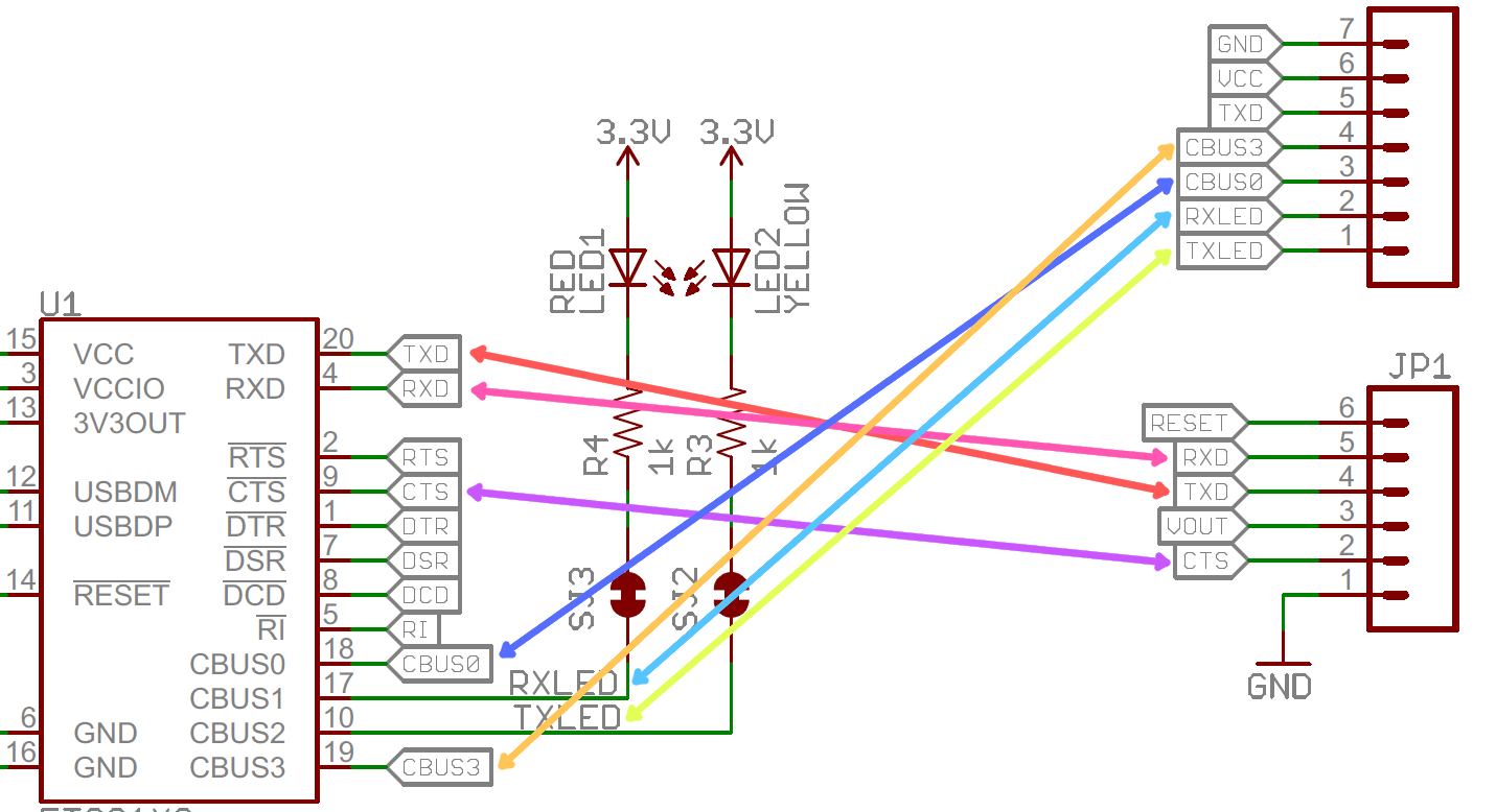
The Guitar Wiring Blog diagrams and tips OnBoard Effects Loop Control
Light Switch Loop Wiring Diagram ElectricsLighting Circuit layouts / A switch loop with an


Light Switch Loop Wiring Diagram Lighthouse Fan Wiring Diagram Wiring Diagram / Building

Loop Powered Instrument Wiring Diagram Wiring Diagram
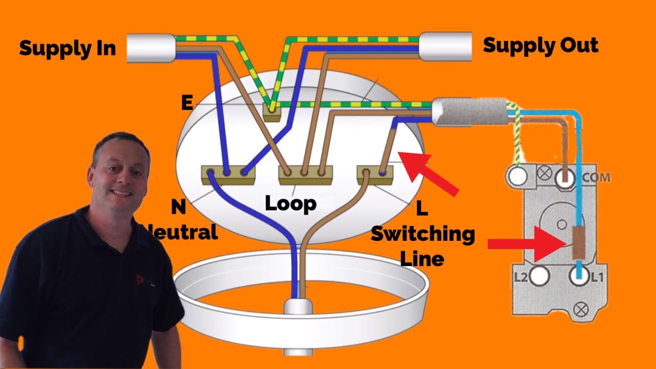
3 Plate LoopIn Method Connections Explained for Wiring a Domestic Lighting Circuit YouTube

Red Wire In Light Switch Box Brilliant Simple 2, Light Switch Wiring Diagram Australia Loop At

Resources
True Bypass Looper Wiring Diagram Wiring Diagram And Schematic Diagram Images
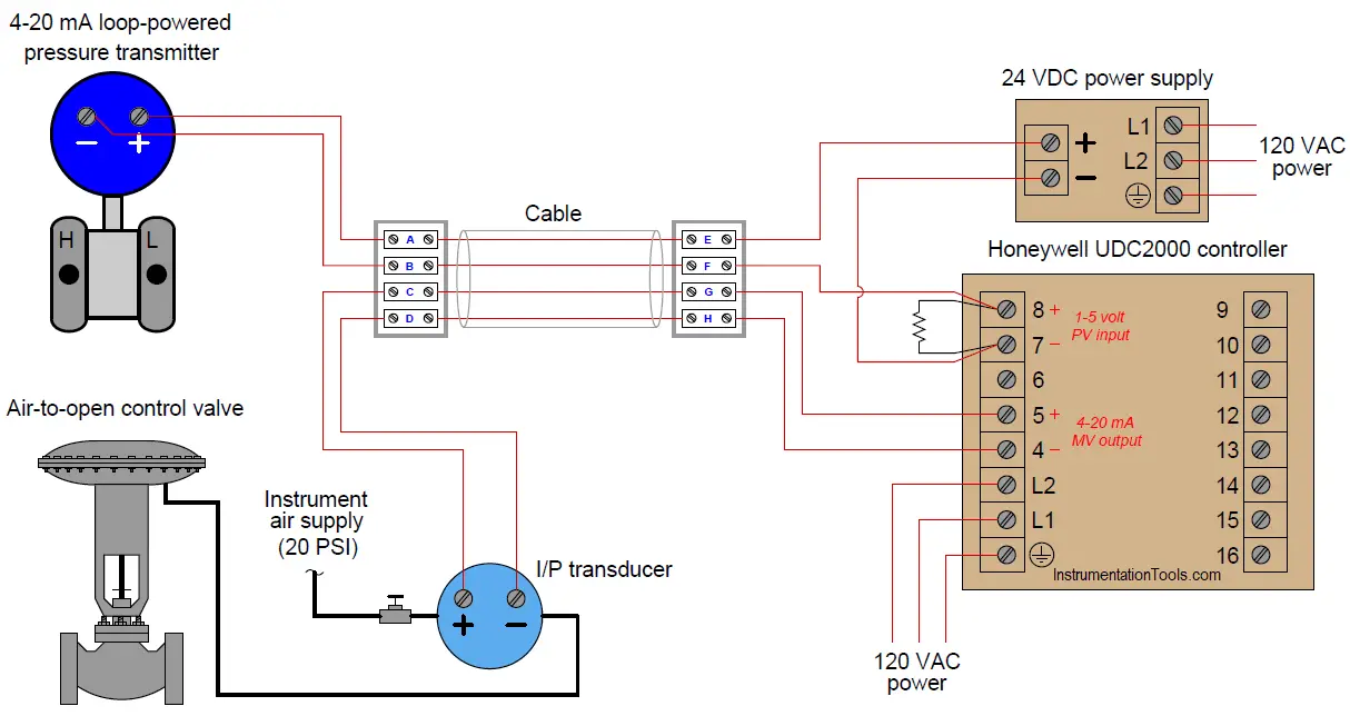
Pressure Control Loop Wiring Connections Instrumentation Tools

Unique Loop Wiring Diagrams diagram wiringdiagram diagramming Diagramm visuals

Light Switch Wiring Common Loop Most LOOP AT, SWITCH 2, LIGHTING WIRING DIAGRAM In Lighting Way

Gallery Of Loop Detector Wiring Diagram Sample
20 Amp Breaker Won't Power Two Lights?? Electrical DIY Chatroom Home Improvement Forum

Loop Wiring Diagram Examples

Basics of The 4 20mA Current Loop Learning Instrumentation And Control Engineering