Traffic Signal Wiring Diagram
October 14, 2010 (may, 2013 update) The full line of solutions includes standard and programmable traffic signals, pedestrian signals, and signal accessories.

Electronic circuit projects, Traffic light, Electronics circuit
10.2 traffic signal conduits all underground signal wiring shall be encased in conduit to protect the cables or conductors and facilitate maintenance.

Traffic signal wiring diagram. Signal warrant analysis, engineering study, and design process the following guidelines describe the typical process for the determination and basis of design for a typical traffic signal within the city of puyallup. Traffic signal design manual and technical specifications 3 of 55 4/21/2010 ii. Wiring diagram complements equipment pad wiring diagram if that is given in detail sheets.
1 trick that we 2 to printing a similar wiring plan off twice. Sequential phases in a ring are not permitted to be on at same time. Relay 4 can be an arrow or light.
Green to red to amber to amber + relay 4, back to green. Econolite ts2 cabinet wiring diagram. Bureau of maintenance and operations.
Switch setting 13, diagram d. Yellow or black polycarbonate housing. The circuit utilizes easily available electronic parts.
Ada bda 3′ 6′ 3′ 30′ 6′ 24′ 6′ traffic A wiring diagram is a streamlined conventional pictorial representation of an electric circuit. Program the traffic signal controller and awegs controller.
April 2, 2018 by headcontrolsystem variety of traffic signal cabinet wiring diagram. Provides this manual for its licensees ts2 type 2 or legacy ts1 connector. The signal designer shall set up a meeting with the
Is the most current and appropriate version as posted on mn/dot web page? Risers), unless the wiring is inside of a pole or attached to a span wire or a messenger cable. All signal wiring above ground shall be installed in conduit (e.g.
Field leads entering a traffic signal control or lighting system Traffic light with a walk, don't walk signal and flashing don't walk. The engineer shall provide three detailed sets of the traffic signal cabinet wiring diagrams to the city of minot.
Additionally, auto table/cadig shall be used to. Here the simple traffic light controller which is could be used to educate kids rudiments of traffic light guidelines. Green to amber to relay 4 to red, back to green.
Nema signal phasing ring 1 1 2 3 4 ring 2 5 6 7 8 ring 1 1 2 3 4 ring 2 5 6 7 8 ring 1 1 2 3 4 ring 2 5 6 7 8. Traffic signal pole wiring connector detail. Default cu ts 2 channel mapping.
Schematic diagrams of the circuitries shall be included in the wiring diagram submittal. System in accordance with the field wiring diagram shown in the plans. Indications read right to left.
Advance loops two advance inductive loops should be installed per lane for both the arterial approaches. It reveals the elements of the circuit as simplified forms, as well as the power and signal links between the tools. Shows four types of loop detector wiring diagrams that are used on odot detector plans.
This is our popular hp200 series signal paired with our 4 position manual control station to make the most reliable safety signal system available! The diagram shown in the top right is for temporary (one. In ring one phases 1,2,3 and 4 should not be programmed to be on at same time.
Diagram top left is the most common one used for traffic signals. Nema traffic signal controller cabinets nema ts2 specifications (doc) english controller cabinets designed for ultimate ease in configuration and installation. Baldwinsours 33x wiring diagram 2:
Built to last in any environment, mccain offers an extensive signal portfolio for most applications. Conduit ped diagram and phasing signal face chart scale pole numbering starts at the cabinet going clockwise. Signal design reference packet (sdrp) the purpose of this packet is to provide guidance on designing and reviewing traffic signal, pedestrian hybrid beacon, and ramp meter plans.
Econolite offers an extensive, high quality line of nema ts1 and ts2. Therefore there will be multiple entries in the ring barrier diagram for these heads (as shown below). The format, legends, tem tables/charts, page layouts, and sample details presented shall be used and followed as shown.
Gr pole notes loop detector detector chart construction notes. Print the wiring diagram off plus use highlighters to trace the signal. Switch setting 8, 9 for eur, wiring diagram d.
Date may 2011 page 3. Switch setting 12, wiring diagram d. Approximately three feet of slack cable must be left in each handhole that houses a cable run and approximately two feet of slack cable must be left in each mast arm pole base, light standard base and pedestal base.
Simplified controller cabinet wiring diagram. Figure 4 illustrates the configuration of the pair of loops in each lane where ada and bda are the names of the two loops. See phases 1, 2, 5, 6 (and associated overlaps a & c) in figure 1, for an example of how protected/permissive fyas should look in the ring barrier diagram.
Traffic light wiring diagram from www.engineersgarage.com. When you make use of your finger or perhaps the actual circuit with your eyes, it is easy to mistrace the circuit. Includes in the color code any conductors unique to the installation.
Place the wiring diagram in the signed cabinet at.

Wiring Diagram For Traffic Lights
Traffic Signal Wiring Diagram General Wiring Diagram

Traffic Signal Wiring Diagram For Your Needs

traffic lights signals controller [Traffic light controller using tranistors] Traffic light
Schematic Traffic Light Wiring Diagram Wiring Diagram Schemas

Schematic Traffic Light Wiring Diagram Wiring Diagram Schemas

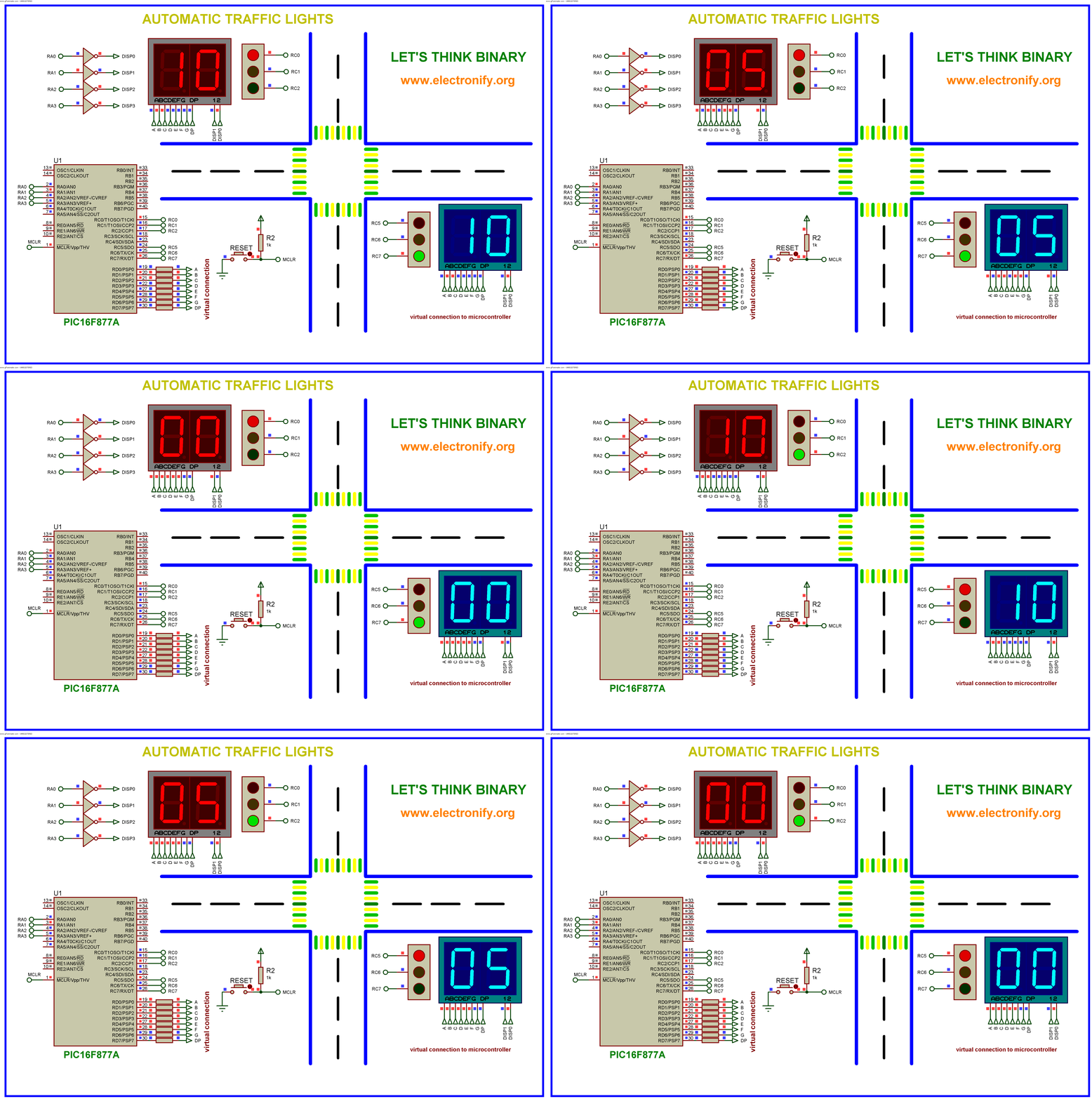
Automatic traffic light using PIC16F877A Microcontroller
Traffic Light Controller under MCU Circuits 5910 Next.gr
Traffic Signal Wiring Diagram Free Wiring Diagram

Traffic Signal Wiring Diagram For Your Needs
Traffic Signal Wiring Diagram Atkinsjewelry

Traffic Signal Wiring Diagram Free Wiring Diagram
Traffic Signal Wiring with Arduino Controller Use Arduino for Projects

31 Traffic Signal Wiring Diagram Wiring Diagram Database
Traffic Signal Wiring Diagram General Wiring Diagram


